Lab 02 — PIR Sensor Integration, Event Logging, and Understanding Sensor Behavior
Deadlines:
- End of lab session (GitHub checkpoint): commit & push your progress to your team repository.
- Before next lab (eClass submission): upload (1) a
.zipwith your code and (2) a PDF export oflabs/lab02/README.md.
Submission contents: (1) a .zip with your code, and (2) a PDF export of labs/lab02/README.md.
Part A — Understanding the sensor device
A.0 Introduction
In Lab 01 you produced clean, high-level events (JSON Lines) without real hardware (beyond the Pi itself).
In Lab 02 we move down the stack:
- A real sensor produces a raw electrical signal (HIGH/LOW).
- Your software must convert that raw signal into meaningful motion events.
- You will still produce structured output (JSONL) so downstream systems can consume it.
Key idea:
A sensor does not produce “events”. It produces signals. Software decides what those signals mean.
This lab is also designed to force you to practice requirements thinking:
- sensor behavior implies software constraints (cooldowns, debouncing, time windows)
- environment affects results (placement, distance, heat sources)
- configuration changes semantics (jumper mode + potentiometers)
By the end of Lab 02 you should be able to:
- Wire the HC‑SR501 correctly and safely to a Raspberry Pi 5.
- Read GPIO input reliably and verify basic sensor behavior.
- Explain the PIR’s warm-up time, reset time, and the effect of its configuration controls.
- Implement a small driver layer (beyond “print HIGH/LOW”).
- Emit structured motion events with correct sequencing and timestamps.
- Demonstrate correctness via small tests and documented evidence.
- Use GitHub Projects (Kanban) to manage tasks and team coordination.
A.1 Introduction to the HC‑SR501 sensor and its interface
Any object with a temperature above absolute zero emits heat energy in the form of radiation. This radiation isn’t visible to the human eye because it radiates at infrared (IR) wavelengths, below the spectrum that people can see.
A measurement of IR energy is not the same as measuring temperature. Temperature measurements rely upon thermal conductance, so when a person enters a room they don’t immediately raise the room temperature. They do, however, have a unique IR “signature” due to their body temperature, and it is that signature that a PIR sensor is looking for.
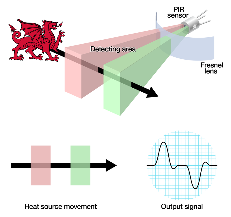
A Passive Infrared (PIR) motion detector works by:
- adjusting itself to the “normal” IR heat signature in its field of view, then
- detecting abrupt changes to that IR signature caused by movement of warm bodies.
To sense infrared energy the detector uses a pyroelectric sensor, which generates an electrical signal in response to receiving IR energy.
Because the detector does not emit energy (unlike ultrasonic sensors), it is called passive: it sits there and “listens” for changes.
When a change is detected, the PIR triggers an alert by changing its output signal.
Illustration:
A.1.1 The HC‑SR501 module (what it provides)
The HC‑SR501 is an inexpensive, self-contained PIR sensor module. It includes:
- on-board signal conditioning,
- a voltage regulator (so it can be powered from a wider range),
- a digital output pin you can connect to microcontrollers/microcomputers.
Typical characteristics:
- detection range adjustable from ~3m to ~7m (environment-dependent),
- output high time adjustable from ~3s to ~300s,
- power input from ~4.5V to ~20V (we will use the Pi’s 5V rail).
A.1.2 Pins (electrical interface)
The HC‑SR501 has a 3‑pin connector:
- VCC: +4.5V to 20V DC input (we will use the Pi’s 5V pin)
- OUT: 3.3V logic output
- LOW = no motion detected
- HIGH = motion detected
- GND: ground
Pinout example image:

A.1.3 Configuration controls (what they change and why software must care)
There are also two potentiometers on the board to adjust parameters:
-
SENSITIVITY potentiometer
Sets the maximum detection distance (approx. 3m to 7m). Real range depends on room topology and placement. -
TIME potentiometer
Sets how longOUTstays HIGH after detection: ~3s to ~300s (5 minutes).
Finally the board has a jumper (on some models it is not soldered). It has two settings:
- Mode jumper
- H (Hold / Repeat): output remains HIGH as long as it continues to detect movement
- L (Intermittent / No‑Repeat): output stays HIGH for the period set by TIME, then returns LOW (even if motion continues)
Operational behavior (important constraints for your program):
- Warm-up: after power-up the PIR needs 30–60 seconds to acclimatize to the room IR level.
- Reset period: after a detection it has a ~5–6 second period during which it will not detect motion.
A.2 Report Questions (A)
Answer briefly, but concretely.
- RQ1: Is a PIR sensor active or passive? Contact or no-contact? Explain in your own words.
- RQ2: What is the output range/representation of this sensor?
- RQ3: If TIME is set to 300s, what wrong assumption might your software make about “continuous motion”?
- RQ4: Why does warm-up time matter in real deployments?
Part B — Raspberry Pi GPIO basics (what you are controlling, which pins to use, and why)
B.0 What is GPIO on the Pi?
GPIO means General Purpose Input/Output. The Raspberry Pi 5 exposes a 40‑pin header. Each pin is one of these categories:
- Power pins
- 5V pins (physical pins 2 and 4)
- 3.3V pin (physical pin 1)
- Ground pins (GND)
- Several pins are GND (for example physical pins 6, 9, 14, 20, 25, 30, 34, 39).
- GPIO pins (signal pins)
- These are the pins your software can read/write (inputs/outputs), e.g., GPIO17, GPIO18, GPIO23, etc.
Raspberry Pi GPIO header reference:

What pins you should use in this lab (practical guidance)
You need exactly three connections:
-
Sensor VCC → Pi 5V (pin 2 or 4)
Why: the HC‑SR501 has an onboard regulator and is designed to run from ~5V; many boards behave unreliably on 3.3V. -
Sensor GND → Pi GND (any ground pin, e.g., pin 6)
Why: GND is the shared voltage reference. Without shared ground, the Pi cannot interpret OUT reliably. -
Sensor OUT → Pi GPIO input pin (choose one GPIO pin, e.g., GPIO17)
Why: OUT is the digital signal your program reads.
Which GPIO input pin should you pick?
For this lab, pick a “simple” GPIO that is not commonly reserved for special functions and is easy to find on the header. Good choices:
- GPIO17 (BCM) → physical pin 11 (recommended default)
- GPIO27 (BCM) → physical pin 13
- GPIO22 (BCM) → physical pin 15
- GPIO23 (BCM) → physical pin 16
- GPIO24 (BCM) → physical pin 18
- GPIO25 (BCM) → physical pin 22
Avoid using pins with common special roles unless you know what you are doing:
- I2C pins (GPIO2/GPIO3), SPI pins (GPIO7–GPIO11), UART pins (GPIO14/GPIO15). They can still work, but they are easier to accidentally conflict with.
In this lab:
- the PIR module drives OUT HIGH/LOW,
- the Pi reads that level on a chosen GPIO input pin.
B.1 Logic levels (critical safety rule)
The Pi’s GPIO uses 3.3V logic.
- LOW ≈ 0V
- HIGH ≈ 3.3V
[!DANGER] Never feed 5V into a GPIO input pin. You can permanently damage the Pi.
The HC‑SR501 OUT is specified as 3.3V logic, which is why it is safe to connect directly to a Pi GPIO input.
B.2 Pin numbering: BCM vs BOARD (and how to not get confused)
There are two naming schemes:
-
BCM numbering
You refer to pins by their GPIO number:GPIO17,GPIO23, etc. -
BOARD numbering
You refer to pins by their physical position number on the header:11,16, etc.
Example mapping:
- BCM GPIO17 = BOARD physical pin 11
Why this matters:
- Your code must match your wiring.
- If you wire to physical pin 11 but your code reads “pin 11” in BCM mode, you will read the wrong signal (and spend 30 minutes debugging nothing).
Rule: Use BCM numbering everywhere (wiring notes + code + README).
- RQ5: Explain a realistic bug that happens when a team mixes BCM and BOARD numbering.
Part C — Wiring the PIR sensor (step-by-step) and verifying hardware
C.0 Goal and mindset (hardware first)
Before writing software, you must build a correct circuit. Software cannot fix incorrect wiring.
For this circuit to work, three things must be true:
- The sensor must be powered (VCC and GND connected).
- The sensor and Pi must share a common reference (GND shared).
- The sensor signal must reach a readable pin (OUT → a GPIO input).
If any of the above is missing, your code will produce misleading results (e.g., random HIGH/LOW flicker, always LOW, always HIGH).
C.1 Safety and setup checklist (do this before plugging wires)
-
Power down or unplug the Pi while wiring (recommended).
Why: prevents accidental short-circuits and protects the board. -
Place the Pi on a non-conductive surface (wood/plastic).
Why: metal tables and loose wires are a bad combination. -
Confirm you know which side of the header is pin 1.
Why: many wiring mistakes come from flipping the pinout mentally.
Pin 1 is the 3.3V pin (top corner of the header in most diagrams). Use the official pinout diagram from Part B to orient yourself.
C.2 Wiring (required)
Connect the HC‑SR501 as follows:
- Sensor VCC → Pi 5V (physical pin 2 or 4)
- Sensor GND → Pi GND (any GND, e.g., physical pin 6)
- Sensor OUT → Pi GPIO input (choose one, e.g., GPIO17 = physical pin 11)
Why each connection exists:
- VCC powers the sensor circuitry.
- GND is the shared reference: without it, HIGH/LOW levels have no meaning.
- OUT is the digital motion signal.
[!IMPORTANT] Power the sensor from 5V. Many HC‑SR501 boards behave poorly at 3.3V.
Common wiring mistakes (read this if in the later sections it “doesn’t work”)
- OUT connected to 5V (wrong; bypasses GPIO and can cause damage)
- VCC connected to 3.3V (often unreliable behavior)
- GND not connected (floating signal; random readings)
- Using BOARD pin numbers in code while wiring by BCM (or vice versa)

C.3 Document your wiring (required)
In your report, include a small wiring table like this:
| Sensor pin | Pi pin (physical) | Pi name (BCM) | Why |
|---|---|---|---|
| VCC | 2 | 5V | power |
| GND | 6 | GND | reference |
| OUT | 11 | GPIO17 | input signal |
- RQ6: Fill in the wiring table for your setup (use your actual pins).
- RQ7: Which GPIO pin did you select (BCM) and why?
C.4 First software smoke-test: “Is the sensor connected?” (very simple)
Before you build the full raw reader and driver, run a minimal program that prints a message when motion is detected.
This answers one question only:
“Is the sensor wired correctly and producing any readable signal on the GPIO pin?”
Why we do this:
- It is faster to debug wiring with a tiny program than with a full logger.
- It prevents wasting time debugging “software bugs” that are actually wiring problems.
Step 1: wait for warm-up
After powering the PIR sensor, wait 60 seconds.
During warm-up the output can be unstable; if you test too early you can confuse “warm-up noise” with “wiring problems”.
Step 2: implement pir_smoke_test.py
Create a new file:
labs/lab02/pir_smoke_test.py
Requirements:
- prints a startup message (pin number)
- prints ONLY when motion is detected (do not spam output continuously)
- exits cleanly on Ctrl-C
Example implementation (gpiozero + callbacks):
from gpiozero import MotionSensor
from signal import pause

# IMPORTANT: Use your chosen BCM GPIO pin here (example: 18)
pir = MotionSensor(18)

def motion_function():
    print("Motion Detected")

def no_motion_function():
    print("Motion stopped")

pir.when_motion = motion_function
pir.when_no_motion = no_motion_function

pause()  # keep the program running
Run it:
python pir_smoke_test.py
If your OUT wire is not on GPIO18, edit the line pir = MotionSensor(18) to your chosen BCM pin.
What “success” looks like:
- After warm-up, moving in front of the sensor prints
MOTION detected - After some time, it prints
Motion stopped(depends on TIME knob and mode)
What “failure” looks like:
- Nothing ever prints, even after warm-up and moving close
C.4 Debug checklist if it doesn’t work
- Confirm
pir = MotionSensor(pin)matches the GPIO you wired OUT to (BCM numbering). - Re-check VCC is on 5V, not 3.3V.
- Re-check GND is connected.
- Wait full warm-up.
- Ask a TA before trying random “fixes” from the internet.
Report questions (smoke test)
- RQ8: Paste the command you ran for the smoke test and a short snippet of output.
C.5 “Play” with the sensor knobs (observe how hardware changes semantics)
Now that you know the sensor is connected, you will intentionally change hardware settings and observe their effect.
Why we do this:
- The same sensor can produce very different output signals depending on configuration.
- Your software driver must be designed with these behaviors in mind.
Knob 1: TIME (output HIGH duration)
Procedure:
- Set TIME to minimum.
- Trigger one motion event (wave your hand).
- Measure how long OUT stays HIGH (watch the smoke-test output).
- Repeat with TIME at maximum.
What you should learn:
- TIME changes how long the sensor looks “active” even if motion stops.
Knob 2: SENSITIVITY (detection distance)
Procedure:
- Set sensitivity low; stand ~1m away and move.
- Increase distance slowly (2m, 3m, …).
- Repeat with sensitivity high.
What you should learn:
- The detection range depends on environment and placement, not only the potentiometer.
Jumper mode: H vs L
Procedure:
- In H mode, keep moving slowly for several seconds.
- In L mode, do the same.
What you should learn:
- H mode tends to keep HIGH “as long as motion continues”
- L mode tends to keep HIGH for a fixed TIME window
Report questions (knob experiments)
- RQ9: With TIME at minimum, approximately how long did OUT remain HIGH after motion?
- RQ10: With TIME at maximum, approximately how long did OUT remain HIGH after motion?
- RQ11: What was the maximum distance at which you reliably triggered motion at low sensitivity vs high sensitivity?
- RQ12: Describe the observed difference between H and L mode in your own words (based on your experiment).
Part D — Software setup
D.0 Same rule as Lab 01: use a venv
You must use a Python virtual environment (venv) exactly as in Lab 01.
Why: reproducibility. If your dependencies differ, your behavior can differ.
From the Raspberry Pi (SSH into the Pi, then go to your repo):
cd <your-repo>/labs/lab02
python3 -m venv venv
source venv/bin/activate
python -c "import sys; print(sys.executable)"
Expected: sys.executable points inside .../labs/lab02/venv/....
Create requirements.txt (we will use gpiozero which is built-in for the pi, but it is good for others to know about its use):
gpiozero==2.0.1
- RQ13: Paste your
sys.executableoutput and explain how it proves you are using the venv.
Part E — From “signal” to “event” (core programming)
E.0 What’s the problem we are solving?
Your PIR sensor does NOT output “events”. It outputs a signal:
- LOW: no detection
- HIGH: detection
But depending on the TIME knob and H/L mode, HIGH can remain HIGH for seconds or minutes.
If you naïvely print/log every time you see HIGH you may get:
motion detected
motion detected
motion detected
motion detected
...
That is not useful data. It is log noise.
So you will implement a small software layer that converts the signal into something meaningful for an application.
E.1 What you will build
You will create a mini library that both programs use (based on code given to you) It is suggested that you read the section until the report questions once, and then try to implement the code asked:
-
pirlib/sampler.py
Reads raw GPIO signal (HIGH/LOW) from the Pi using gpiozero. -
pirlib/interpreter.py
Applies interpretation logic (anti-spam + filtering) and returns semantic events.
Then you will create two programs:
-
pir_print.py
Human-readable “what events am I producing?” tool. -
pir_event_logger.py
Lab-01-style JSONL logger (append-only, seq/run_id, timestamps, Ctrl-C safe).
Required structure:
labs/lab02/
├── pirlib/
│   ├── __init__.py
│   ├── sampler.py
│   └── interpreter.py
├── pir_print.py
├── pir_event_logger.py
└── README.md
E.2
In the lecture we emphasized: device behavior forces software decisions. Here are the concrete ones you will implement.
E.2.1 Technique 1: Sampling rate (polling strategy)
Your code will “check” the sensor periodically. That period is a design choice.
- Too slow → you can miss short events (especially if TIME is minimum).
- Too fast → you spam output and amplify noise; waste CPU; write too much data.
Requirement:
- Both programs must support
--sample-interval. (time between consecutive sensor reads)
E.2.2 Technique 2: Anti-spam semantics (“one event per detection window”)
This is the most sensor-appropriate improvement.
Requirement:
- Your interpreter must log only one event while OUT is HIGH, and only log again after it goes LOW.
We call this policy:
once_per_high: emit one"motion_detected"per HIGH window.
Why it matches the PIR:
- TIME knob can make HIGH last long; this prevents repeated “motion detected” spam.
E.2.3 Technique 3: Cooldown (debounce/rate limiting)
Even with once-per-high, some setups can retrigger rapidly (or you may want to enforce a minimum gap between events).
Requirement:
- Support
--cooldownseconds. - After emitting an event, ignore new “eligible” events for cooldown duration.
Why:
- matches PIR reset behavior (~5–6 seconds)
- reduces duplicates
E.2.4 Technique 4: Minimum HIGH filter (noise/spike filtering)
Sometimes you may observe brief HIGH spikes (especially during warm-up or noisy environments).
Requirement:
- Support
--min-highseconds. - Only emit a motion event if the signal stays HIGH for at least
min_high.
Why:
- This is a simple, standard filtering technique (debounce/glitch filter).
E.2.5 Technique 5: Timestamps and latency (observability)
Like Lab 01, you will include:
event_time: when the event occurred (in software)ingest_time: when you wrote it to the log
Requirement:
- JSONL records include both timestamps (UTC ISO format).
- You compute a small “latency estimate” (ingest_time - event_time) for at least 3 records in your report.
Skeleton for pirlib/sampler.py (gpiozero raw reader)
We use polling (DigitalInputDevice) because it’s simple and works well with sampling intervals.
from gpiozero import DigitalInputDevice

class PirSampler:
    def __init__(self, pin: int):
        self.pin = pin
        self.dev = DigitalInputDevice(pin)

    def read(self) -> bool:
        # True = HIGH, False = LOW
        return bool(self.dev.value)
Skeleton for pirlib/interpreter.py (the “brain”)
Design goal:
update(raw, t)returns a list of semantic events (often empty).
Simple rule:
- Only emit
motion_detectedonce per HIGH window, - but only after HIGH has persisted for
min_high, - and only if not in cooldown.
Skeleton:
from typing import Optional, List, Dict

class PirInterpreter:
    def __init__(self, cooldown_s: float = 0.0, min_high_s: float = 0.0):
        self.cooldown_s = cooldown_s
        self.min_high_s = min_high_s

        self.prev_raw = False
        self.high_start_t: Optional[float] = None
        self.emitted_for_this_high = False
        self.last_emit_t: Optional[float] = None

    def update(self, raw: bool, t: float) -> List[Dict]:
        events: List[Dict] = []

        rising = (not self.prev_raw) and raw
        falling = self.prev_raw and (not raw)

        if rising:
            self.high_start_t = t
            self.emitted_for_this_high = False

        if falling:
            self.high_start_t = None
            self.emitted_for_this_high = False

        # If currently HIGH and we haven't emitted yet, check min_high and cooldown
        if raw and (not self.emitted_for_this_high) and (self.high_start_t is not None):
            high_for = t - self.high_start_t
            if high_for >= self.min_high_s:
                in_cd = self.last_emit_t is not None and (t - self.last_emit_t) < self.cooldown_s
                if not in_cd:
                    events.append({"kind": "motion_detected", "t": t})
                    self.last_emit_t = t
                    self.emitted_for_this_high = True

        self.prev_raw = raw
        return events
E.3 Program 1: pir_print.py (human-readable event stream)
Purpose:
- quick feedback for humans
- lets you see whether your interpreter behaves correctly under different TIME/SENS/H-L settings
CLI requirement:
python pir_print.py --pin 18 --sample-interval 0.1 --cooldown 5 --min-high 0.2 --duration 60
Rules:
- Print only interpreted events (not raw samples)
- Include time since start in prints
- Ctrl-C exits cleanly
Example:
import time, argparse
from pirlib.sampler import PirSampler
from pirlib.interpreter import PirInterpreter

def main():
    p = argparse.ArgumentParser()
    p.add_argument("--pin", type=int, required=True)
    p.add_argument("--sample-interval", type=float, default=0.1)
    p.add_argument("--cooldown", type=float, default=0.0)
    p.add_argument("--min-high", type=float, default=0.0)
    p.add_argument("--duration", type=float, default=30.0)
    args = p.parse_args()

    sampler = PirSampler(args.pin)
    interp = PirInterpreter(cooldown_s=args.cooldown, min_high_s=args.min_high)

    t0 = time.time()
    end = t0 + args.duration

    print(f"[print] pin={args.pin} interval={args.sample_interval}s cooldown={args.cooldown}s min_high={args.min_high}s")

    try:
        while time.time() < end:
            now = time.time()
            raw = sampler.read()
            for ev in interp.update(raw, now):
                print(f"t={ev['t']-t0:7.2f}s {ev['kind']}")
            time.sleep(args.sample_interval)
    except KeyboardInterrupt:
        print("\n[print] Ctrl-C: exit.")

if __name__ == "__main__":
    main()
E.4 — Program 2: pir_event_logger.py (JSONL logger, Lab 01 style)
This is your main deliverable.
It must:
- accept CLI args (device_id, pin, sample interval, cooldown, min_high, duration, out)
- validate args and use exit codes (2 usage, 1 runtime)
- write JSONL append-only
- include
seqandrun_id - include
event_timeandingest_time(UTC) - handle Ctrl-C safely and report written count
CLI example:
python pir_event_logger.py --device-id pir-01 --pin 18 --sample-interval 0.1 --cooldown 5 --min-high 0.2 --duration 60 --out motion_events.jsonl --verbose
Required JSONL fields:
event_time,ingest_time,device_idevent_type="motion"motion_state="detected"seq,run_idRecommended:pin,sample_interval_s,cooldown_s,min_high_s
Timestamp helper (Lab 01 style):
from datetime import datetime, timezone

def utc_now_iso() -> str:
    return (
        datetime.now(timezone.utc)
        .isoformat(timespec="milliseconds")
        .replace("+00:00", "Z")
    )
- RQ14: What sample interval did you choose and why? (Use your knob experiments to justify it.)
- RQ15: What cooldown did you choose and why?
- RQ16: Did you observe brief spikes? What
min_highdid you choose (or why did you keep it 0)? - RQ17: Compute and report latency for 3 records.
- RQ18: In your own words, explain how your interpreter prevents “motion detected” spam.
- RQ19: Show a short output snippet of pir_print.py
- RQ20: Show a short output snippet of pir_event_logger.py
Part F — GitHub Projects Kanban Board (in your repo): what it is, why we use it, and exactly how to do it
Hardware + software work fails most often because teams lose track of “who is doing what” and “what is actually done”.
A Kanban board makes work visible, prevents duplicate effort, and forces you to define “done” clearly.
In this lab, your board is part of the deliverable.
F.0 What you are creating
You will create a GitHub Project (Kanban board) for your team repository with three columns:
- Backlog
- In Progress
- Done
Each card represents a concrete piece of lab work (wiring, experiments, code modules, tests, README answers).
F.1 Step-by-step: create the Project board in your repository
Step 1 — Open your repository on GitHub
- Go to your team repo in the browser.
- Make sure you are in the correct repo (not your personal profile).
Step 2 — Create a Project
- Click the Projects tab (top menu).
- If you do not see it, click More (…) and find Projects.
- Click New project.
- Choose Board (Kanban style).
- Name it: Lab02 – PIR Sensor Kanban (or similar).
- Click Create.
Step 3 — Create the columns
Most board templates start with “Todo / In progress / Done”. Rename them to:
- Backlog
- In Progress
- Done
(If extra columns exist, delete them or keep only these three.)
F.2 Step-by-step: add cards (issues) to the board
There are two ways to create cards:
Option A (recommended): cards are GitHub Issues
Pros: issues can be assigned, discussed, referenced by commits/PRs.
How:
- In the board, click + Add item under Backlog.
- Type a short title and press Enter.
Example:Implement pirlib/interpreter.py (cooldown + min_high) - Click the created item → choose Convert to issue (or “Open in new tab” then “Create issue”).
- Assign it to a teammate and add a short checklist.
Option B: draft items (no issue)
Pros: fast.
Cons: harder to assign/track; less integration.
For this lab, use Option A for at least the main tasks.
F.3 The required cards for Lab 02 (minimum)
Create these cards in Backlog \ In Progress \ Done etc.:
- Wiring verified (wiring table completed + photo/diagram)
- Smoke test works (
pir_smoke_test.pyprints motion/no-motion) - Knob experiments recorded (TIME min/max, SENS min/max, H vs L)
- pirlib/sampler.py implemented
- pirlib/interpreter.py implemented (once_per_high + cooldown + min_high)
- pir_print.py implemented (uses pirlib, prints only events)
- pir_event_logger.py implemented (JSONL append-only + seq + run_id + timestamps)
- Mini-tests evidence in tests.md
- README report questions answered (Lab 02)
F.4 What “Done” means (acceptance criteria)
A card is allowed to move to Done only if:
- It runs on the Pi
- It is committed and pushed to GitHub.
- It has evidence if relevant (output snippet, wiring table, etc.)
Add 2–4 acceptance checklist items in each issue. Example:
For pir_event_logger.py implemented:
- CLI runs with required args
- JSONL file contains valid JSON per line
- seq increments by 1 per record (per run)
- Ctrl-C exits cleanly without corrupting the last line
F.5 A simple required exercise (do this today)
Complete this mini-workflow:
- Create the Project board.
- Add the cards from above.
- Convert at least 3 of them into Issues.
- Assign at least one issue to each teammate.
- Add acceptance checklists to:
pirlib/interpreter.py implementedpir_event_logger.py implemented
- Move Smoke test works to Done once you have pushed the smoke test and pasted output in
tests.md.
F.7 Practical tip: connect commits/PRs to issues
If you use GitHub Issues, you can reference them in commit messages and PRs:
- Commit message example:
Lab02: implement PIR interpreter (#12) - PR description:
Closes #12
This automatically links work to tasks and makes grading/debugging easier.
- RQ21: Provide a screenshot of your board .
- RQ22: Give one concrete example of how the board can prevent a coordination bug (e.g., wrong pin, duplicated work, missed experiment).
- RQ23: Which card can be a “critical path” blocker for your team, and why?
Project hint (Smart Wastebin)
Lab 02 produces a component you will reuse in the Smart Wastebin project: a motion event stream.
What you build in this lab becomes the project’s “motion sensing layer”:
- PIR sensor → raw HIGH/LOW signal
- pirlib → defines clean semantics (anti-spam + filtering + cooldown)
- pir_event_logger.py → outputs structured JSONL motion events
In the project later, other parts of your system will consume these events to make decisions (e.g., “bin was used”).
The important project lesson:
- the sensor’s knobs (TIME / SENS / H-L) change raw behavior,
- your software layer must stay stable and produce meaningful events anyway.
So Lab 02 teaches how to use the motion sensor. Also we recommend creating a GitHub Projects board as a “project dashboard” for the whole semester.
Final checklist (Lab 02)
- Sensor wired correctly and wiring is documented
- venv exists
-
pirlib/implemented (sampler + interpreter) -
pir_print.pyprints only events -
pir_event_logger.pywrites append-only JSONL withseq,run_id,event_time,ingest_time - GitHub Projects board used (Backlog / In Progress / Done)
- eClass package prepared:
.zip+lab02_README_<team>.pdf
Deliverables and Submission
WARNING! DO NOT MODIFY THE CODE INSIDE LAB01
What must exist in the repository (by end of lab)
Your repository must contain at least:
/
/
├── README.md
├── labs/
│   ├── lab01/
│   └── lab02/
│       ├── README.md
│       ├── requirements.txt
│       ├── pir_smoke_test.py
│       ├── pir_print.py
│       ├── pir_event_logger.py
│       ├── pirlib/
│       │   ├── __init__.py
│       │   ├── sampler.py
│       │   └── interpreter.py
Required files:
- labs/lab02/ (entire folder)
- labs/lab02/requirements.txt
- labs/lab02/pirlib/ (your mini library)
- labs/lab02/pir_print.py (human-readable events)
- labs/lab02/pir_event_logger.py (JSONL logger, Lab 01 style)
- labs/lab02/pir_smoke_test.py (wiring confirmation)
- labs/lab02/README.md (runbook + report)
What labs/lab02/README.md must contain
Your labs/lab02/README.md must contain two clearly separated parts (code, questions) similarly to lab 1 (see lab 1 instructions)
Submission deadlines
1) End of lab session — GitHub checkpoint (required)
Before leaving the lab:
- commit your progress
- push to your team GitHub repository
Minimum expectation for the GitHub checkpoint:
- all required deliverables are tracked by Git
- latest commit is pushed
- commit message is clear (example:
Lab02: setup + motion_detector + README)
2) Before next lab (eClass submission + git submission)
Submit both of the following on eClass:
- Code archive (
.zip) - PDF export of
labs/lab02/README.md
Required PDF filename format:
lab02_REPORT_<team>.pdf
Don’t forget to also submit on your Github Repo.
- Push/submit a final version on GitHub
What to include in the .zip
Include at least:
labs/lab02/(entire folder)- Root
README.md
Do not include:
venv/__pycache__/*.pyc- large logs or temporary files (unless explicitly requested)
What follows is a greek version of the same lab
Εργαστήριο 02 — Ενσωμάτωση Αισθητήρα PIR, Καταγραφή Συμβάντων και Κατανόηση Συμπεριφοράς Αισθητήρων
Προθεσμίες:
- Τέλος εργαστηριακής συνεδρίας (GitHub checkpoint): κάντε commit & push την πρόοδό σας στο ομαδικό repository.
- Πριν το επόμενο εργαστήριο (υποβολή στο eClass): ανεβάστε (1) ένα
.zipμε τον κώδικά σας και (2) ένα PDF export τουlabs/lab02/README.md.
Περιεχόμενα υποβολής: (1) ένα .zip με τον κώδικά σας, και (2) ένα PDF export του labs/lab02/README.md.
Μέρος A — Κατανόηση της συσκευής-αισθητήρα
A.0 Εισαγωγή
Στο Lab 01 παράξατε καθαρά, υψηλού επιπέδου συμβάντα (JSON Lines) χωρίς πραγματικό hardware (πέρα από το ίδιο το Pi).
Στο Lab 02 κατεβαίνουμε πιο χαμηλά στο stack:
- Ένας πραγματικός αισθητήρας παράγει ένα ακατέργαστο ηλεκτρικό σήμα (HIGH/LOW).
- Το λογισμικό σας πρέπει να μετατρέψει αυτό το ακατέργαστο σήμα σε ουσιαστικά συμβάντα κίνησης.
- Θα συνεχίσετε να παράγετε δομημένη έξοδο (JSONL) ώστε τα downstream συστήματα να την καταναλώνουν.
Κεντρική ιδέα:
Ένας αισθητήρας δεν παράγει «events». Παράγει σήματα. Το λογισμικό αποφασίζει τι σημαίνουν αυτά τα σήματα.
Αυτό το εργαστήριο είναι επίσης σχεδιασμένο ώστε να σας «αναγκάσει» να εξασκηθείτε στη σκέψη απαιτήσεων:
- η συμπεριφορά του αισθητήρα συνεπάγεται περιορισμούς στο λογισμικό (cooldowns, debouncing, χρονικά παράθυρα)
- το περιβάλλον επηρεάζει τα αποτελέσματα (τοποθέτηση, απόσταση, πηγές θερμότητας)
- οι ρυθμίσεις αλλάζουν τη σημασιολογία (jumper mode + ποτενσιόμετρα)
Στο τέλος του Lab 02 θα πρέπει να μπορείτε να:
- Καλωδιώσετε σωστά και με ασφάλεια τον HC‑SR501 σε Raspberry Pi 5.
- Διαβάσετε αξιόπιστα GPIO input και να επαληθεύσετε τη βασική συμπεριφορά του αισθητήρα.
- Εξηγήσετε τον χρόνο warm-up, τον χρόνο reset, και την επίδραση των ρυθμιστικών/ρυθμίσεων παραμετροποίησης.
- Υλοποιήσετε ένα μικρό driver layer (πέρα από «print HIGH/LOW»).
- Παράγετε δομημένα motion events με σωστή αλληλουχία και timestamps.
- Δείξετε ορθότητα μέσω μικρών tests και τεκμηριωμένων αποδείξεων.
- Χρησιμοποιήσετε GitHub Projects (Kanban) για διαχείριση εργασιών και συντονισμό ομάδας.
A.1 Εισαγωγή στον αισθητήρα HC‑SR501 και στο interface του
Οποιοδήποτε αντικείμενο με θερμοκρασία πάνω από το απόλυτο μηδέν εκπέμπει θερμική ενέργεια με μορφή ακτινοβολίας. Αυτή η ακτινοβολία δεν είναι ορατή στο ανθρώπινο μάτι, επειδή εκπέμπεται σε μήκη κύματος υπέρυθρης (IR) ακτινοβολίας, κάτω από το φάσμα που μπορούν να δουν οι άνθρωποι.
Η μέτρηση της IR ενέργειας δεν είναι το ίδιο με τη μέτρηση θερμοκρασίας. Οι μετρήσεις θερμοκρασίας βασίζονται στη θερμική αγωγιμότητα, άρα όταν ένας άνθρωπος μπαίνει σε ένα δωμάτιο δεν αυξάνει αμέσως τη θερμοκρασία του δωματίου. Έχει όμως ένα ιδιαίτερο IR «αποτύπωμα» λόγω της θερμοκρασίας σώματος, και αυτό το αποτύπωμα είναι που «ψάχνει» ένας PIR αισθητήρας.
Ένας ανιχνευτής κίνησης Passive Infrared (PIR) λειτουργεί ως εξής:
- προσαρμόζεται στο «κανονικό» IR θερμικό αποτύπωμα στο οπτικό του πεδίο, και στη συνέχεια
- ανιχνεύει απότομες αλλαγές σε αυτό το IR αποτύπωμα που προκαλούνται από κίνηση θερμών σωμάτων.
Για την ανίχνευση της IR ενέργειας χρησιμοποιεί έναν pyroelectric sensor, ο οποίος παράγει ηλεκτρικό σήμα ως απόκριση στη λήψη IR ενέργειας.
Επειδή ο ανιχνευτής δεν εκπέμπει ενέργεια (σε αντίθεση π.χ. με υπερηχητικούς αισθητήρες), λέγεται passive: απλώς «ακούει» για αλλαγές.
Όταν ανιχνευτεί αλλαγή, ο PIR ενεργοποιεί ειδοποίηση αλλάζοντας το output σήμα του.
Εικόνα:
A.1.1 Το module HC‑SR501 (τι προσφέρει)
Το HC‑SR501 είναι ένα φθηνό, αυτοτελές PIR sensor module. Περιλαμβάνει:
- on-board signal conditioning,
- ρυθμιστή τάσης (ώστε να τροφοδοτείται από ευρύτερο εύρος),
- digital output pin για σύνδεση με microcontrollers/microcomputers.
Τυπικά χαρακτηριστικά:
- ρυθμιζόμενη εμβέλεια ανίχνευσης περίπου από ~3m έως ~7m (εξαρτάται από το περιβάλλον),
- ρυθμιζόμενος χρόνος HIGH εξόδου από ~3s έως ~300s,
- είσοδος τροφοδοσίας περίπου ~4.5V έως ~20V (θα χρησιμοποιήσουμε το 5V rail του Pi).
A.1.2 Pins (ηλεκτρικό interface)
Ο HC‑SR501 έχει έναν 3-pin connector:
- VCC: +4.5V έως 20V DC είσοδος (θα χρησιμοποιήσουμε το 5V pin του Pi)
- OUT: 3.3V logic output
- LOW = δεν ανιχνεύτηκε κίνηση
- HIGH = ανιχνεύτηκε κίνηση
- GND: γείωση
Παράδειγμα εικόνας pinout:
A.1.3 Ρυθμιστικά (τι αλλάζουν και γιατί το λογισμικό πρέπει να το «ξέρει»)
Υπάρχουν επίσης δύο ποτενσιόμετρα για ρύθμιση παραμέτρων:
-
Ποτενσιόμετρο SENSITIVITY
Ορίζει τη μέγιστη απόσταση ανίχνευσης (περίπου 3m έως 7m). Το πραγματικό range εξαρτάται από τη γεωμετρία του χώρου και την τοποθέτηση. -
Ποτενσιόμετρο TIME
Ορίζει πόσο χρόνο τοOUTπαραμένει HIGH μετά από ανίχνευση: ~3s έως ~300s (5 λεπτά).
Τέλος, η πλακέτα έχει έναν jumper (σε ορισμένα μοντέλα δεν είναι κολλημένος). Έχει δύο ρυθμίσεις:
- Mode jumper
- H (Hold / Repeat): η έξοδος παραμένει HIGH όσο συνεχίζει να ανιχνεύει κίνηση
- L (Intermittent / No‑Repeat): η έξοδος μένει HIGH για τη διάρκεια που ορίζει το TIME, και μετά επιστρέφει LOW (ακόμα κι αν η κίνηση συνεχίζεται)
Λειτουργική συμπεριφορά (σημαντικοί περιορισμοί για το πρόγραμμά σας):
- Warm-up: μετά την τροφοδοσία, ο PIR χρειάζεται 30–60 δευτερόλεπτα για να «προσαρμοστεί» στο IR επίπεδο του χώρου.
- Reset period: μετά από μία ανίχνευση έχει περίοδο ~5–6 δευτερολέπτων όπου δεν θα ανιχνεύσει κίνηση.
A.2 Ερωτήσεις Αναφοράς (A)
Απαντήστε σύντομα, αλλά συγκεκριμένα.
- RQ1: Είναι ένας PIR αισθητήρας active ή passive; contact ή no-contact; Εξηγήστε με δικά σας λόγια.
- RQ2: Ποιο είναι το output range/representation του αισθητήρα;
- RQ3: Αν το TIME είναι ρυθμισμένο στα 300s, ποια λανθασμένη υπόθεση μπορεί να κάνει το λογισμικό σας για «συνεχή κίνηση»;
- RQ4: Γιατί ο warm-up χρόνος έχει σημασία σε πραγματικές εγκαταστάσεις;
Μέρος B — Βασικά GPIO στο Raspberry Pi (τι ελέγχετε, ποια pins να χρησιμοποιήσετε, και γιατί)
B.0 Τι είναι GPIO στο Pi;
GPIO σημαίνει General Purpose Input/Output. Το Raspberry Pi 5 εκθέτει μια κεφαλίδα 40 pins. Κάθε pin ανήκει σε μία από τις παρακάτω κατηγορίες:
- Pins τροφοδοσίας
- 5V pins (φυσικά pins 2 και 4)
- 3.3V pin (φυσικό pin 1)
- Pins γείωσης (GND)
- Πολλά pins είναι GND (π.χ. φυσικά pins 6, 9, 14, 20, 25, 30, 34, 39).
- GPIO pins (pins σήματος)
- Αυτά είναι τα pins που το λογισμικό σας μπορεί να διαβάσει/γράψει (inputs/outputs), π.χ. GPIO17, GPIO18, GPIO23, κ.λπ.
Αναφορά GPIO header Raspberry Pi:
Ποια pins να χρησιμοποιήσετε σε αυτό το lab (πρακτική καθοδήγηση)
Χρειάζεστε ακριβώς τρεις συνδέσεις:
-
VCC αισθητήρα → 5V του Pi (pin 2 ή 4)
Γιατί: ο HC‑SR501 έχει onboard regulator και είναι σχεδιασμένος για ~5V· πολλές πλακέτες συμπεριφέρονται αναξιόπιστα στα 3.3V. -
GND αισθητήρα → GND του Pi (οποιοδήποτε ground pin, π.χ. pin 6)
Γιατί: το GND είναι η κοινή αναφορά τάσης. Χωρίς κοινό ground, το Pi δεν μπορεί να ερμηνεύσει αξιόπιστα το OUT. -
OUT αισθητήρα → GPIO input pin του Pi (επιλέξτε ένα GPIO pin, π.χ. GPIO17)
Γιατί: το OUT είναι το digital σήμα που διαβάζει το πρόγραμμά σας.
Ποιο GPIO input pin να επιλέξετε;
Για αυτό το lab, επιλέξτε ένα «απλό» GPIO που δεν είναι συνήθως δεσμευμένο για ειδικές λειτουργίες και φαίνεται εύκολα στην κεφαλίδα. Καλές επιλογές:
- GPIO17 (BCM) → φυσικό pin 11 (προτεινόμενο default)
- GPIO27 (BCM) → φυσικό pin 13
- GPIO22 (BCM) → φυσικό pin 15
- GPIO23 (BCM) → φυσικό pin 16
- GPIO24 (BCM) → φυσικό pin 18
- GPIO25 (BCM) → φυσικό pin 22
Αποφύγετε pins με συχνές ειδικές χρήσεις, εκτός αν ξέρετε τι κάνετε:
- I2C pins (GPIO2/GPIO3), SPI pins (GPIO7–GPIO11), UART pins (GPIO14/GPIO15). Μπορούν να δουλέψουν, αλλά είναι πιο εύκολο να προκύψει σύγκρουση κατά λάθος.
Σε αυτό το lab:
- το PIR module οδηγεί το OUT HIGH/LOW,
- το Pi διαβάζει αυτό το level σε ένα επιλεγμένο GPIO input pin.
B.1 Logic levels (κρίσιμος κανόνας ασφάλειας)
Τα GPIO του Pi χρησιμοποιούν 3.3V logic.
- LOW ≈ 0V
- HIGH ≈ 3.3V
[!DANGER] Ποτέ μην δώσετε 5V σε GPIO input pin. Μπορεί να καταστρέψετε μόνιμα το Pi.
Το OUT του HC‑SR501 ορίζεται ως 3.3V logic, γι’ αυτό είναι ασφαλές να συνδεθεί απευθείας σε Pi GPIO input.
B.2 Αρίθμηση pins: BCM vs BOARD (και πώς να μην μπερδευτείτε)
Υπάρχουν δύο schemes:
-
BCM numbering
Αναφέρεστε στα pins με τον αριθμό GPIO:GPIO17,GPIO23, κ.λπ. -
BOARD numbering
Αναφέρεστε στα pins με τη φυσική θέση τους στην κεφαλίδα:11,16, κ.λπ.
Παράδειγμα mapping:
- BCM GPIO17 = BOARD φυσικό pin 11
Γιατί έχει σημασία:
- Ο κώδικάς σας πρέπει να ταιριάζει με την καλωδίωση.
- Αν καλωδιώσετε στο φυσικό pin 11 αλλά ο κώδικάς σας διαβάζει «pin 11» σε BCM mode, θα διαβάσετε λάθος σήμα (και θα χάσετε 30 λεπτά κάνοντας debug… τίποτα).
Κανόνας: Χρησιμοποιήστε BCM numbering παντού (σημειώσεις καλωδίωσης + κώδικας + README).
- RQ5: Εξηγήστε ένα ρεαλιστικό bug που συμβαίνει όταν μια ομάδα αναμειγνύει BCM και BOARD numbering.
Μέρος C — Καλωδίωση του PIR αισθητήρα (βήμα-βήμα) και επαλήθευση hardware
C.0 Στόχος και νοοτροπία (πρώτα το hardware)
Πριν γράψετε λογισμικό, πρέπει να φτιάξετε ένα σωστό κύκλωμα. Το λογισμικό δεν μπορεί να διορθώσει λάθος καλωδίωση.
Για να δουλέψει αυτό το κύκλωμα, τρία πράγματα πρέπει να ισχύουν:
- Ο αισθητήρας πρέπει να τροφοδοτείται (VCC και GND συνδεδεμένα).
- Ο αισθητήρας και το Pi πρέπει να έχουν κοινή αναφορά (κοινό GND).
- Το σήμα του αισθητήρα πρέπει να φτάνει σε αναγνώσιμο pin (OUT → GPIO input).
Αν λείπει κάτι από τα παραπάνω, ο κώδικάς σας θα δώσει παραπλανητικά αποτελέσματα (π.χ. τυχαίο HIGH/LOW flicker, πάντα LOW, πάντα HIGH).
C.1 Checklist ασφάλειας και setup (κάντε το πριν βάλετε καλώδια)
-
Κλείστε/αποσυνδέστε το Pi κατά την καλωδίωση (συνιστάται).
Γιατί: αποτρέπει τυχαία short-circuits και προστατεύει την πλακέτα. -
Βάλτε το Pi σε μη αγώγιμη επιφάνεια (ξύλο/πλαστικό).
Γιατί: μεταλλικά τραπέζια και χαλαρά καλώδια είναι κακός συνδυασμός. -
Επιβεβαιώστε ότι ξέρετε ποια πλευρά της κεφαλίδας είναι το pin 1.
Γιατί: πολλά λάθη καλωδίωσης προκύπτουν από «ανάποδο» νοητικό pinout.
Το pin 1 είναι το 3.3V pin (στην πάνω γωνία της κεφαλίδας στα περισσότερα διαγράμματα). Χρησιμοποιήστε το επίσημο pinout διάγραμμα από το Μέρος B για προσανατολισμό.
C.2 Καλωδίωση (απαιτείται)
Συνδέστε τον HC‑SR501 ως εξής:
- VCC αισθητήρα → 5V του Pi (φυσικό pin 2 ή 4)
- GND αισθητήρα → GND του Pi (οποιοδήποτε GND, π.χ. φυσικό pin 6)
- OUT αισθητήρα → GPIO input του Pi (επιλέξτε ένα, π.χ. GPIO17 = φυσικό pin 11)
Γιατί υπάρχει κάθε σύνδεση:
- Το VCC τροφοδοτεί το κύκλωμα του αισθητήρα.
- Το GND είναι η κοινή αναφορά: χωρίς αυτό, τα HIGH/LOW levels δεν έχουν νόημα.
- Το OUT είναι το digital motion σήμα.
[!IMPORTANT] Τροφοδοτήστε τον αισθητήρα από 5V. Πολλά HC‑SR501 boards έχουν προβληματική συμπεριφορά στα 3.3V.
Συνηθισμένα λάθη καλωδίωσης (διαβάστε το αν αργότερα «δεν δουλεύει»)
- OUT συνδεδεμένο σε 5V (λάθος· παρακάμπτει το GPIO και μπορεί να προκαλέσει ζημιά)
- VCC συνδεδεμένο σε 3.3V (συχνά αναξιόπιστη συμπεριφορά)
- GND μη συνδεδεμένο (floating σήμα· τυχαίες μετρήσεις)
- Χρήση BOARD αριθμών στον κώδικα ενώ καλωδιώνετε με BCM (ή το αντίστροφο)
C.3 Τεκμηριώστε την καλωδίωση (απαιτείται)
Στην αναφορά σας, συμπεριλάβετε έναν μικρό wiring πίνακα όπως αυτός:
| Sensor pin | Pi pin (physical) | Pi name (BCM) | Why |
|---|---|---|---|
| VCC | 2 | 5V | power |
| GND | 6 | GND | reference |
| OUT | 11 | GPIO17 | input signal |
- RQ6: Συμπληρώστε τον wiring πίνακα για το setup σας (χρησιμοποιήστε τα πραγματικά σας pins).
- RQ7: Ποιο GPIO pin επιλέξατε (BCM) και γιατί;
C.4 Πρώτο software smoke-test: «Είναι ο αισθητήρας συνδεδεμένος;» (πολύ απλό)
Πριν φτιάξετε τον πλήρη raw reader και driver, τρέξτε ένα ελάχιστο πρόγραμμα που τυπώνει μήνυμα όταν ανιχνεύεται κίνηση.
Αυτό απαντά μόνο σε μία ερώτηση:
«Είναι ο αισθητήρας σωστά καλωδιωμένος και παράγει οποιοδήποτε αναγνώσιμο σήμα στο GPIO pin;»
Γιατί το κάνουμε:
- Είναι πιο γρήγορο να κάνετε debug την καλωδίωση με ένα μικρό πρόγραμμα παρά με πλήρη logger.
- Αποτρέπει το να σπαταλήσετε χρόνο κάνοντας debug «software bugs» που είναι στην πραγματικότητα λάθη καλωδίωσης.
Βήμα 1: περιμένετε warm-up
Μετά την τροφοδοσία του PIR αισθητήρα, περιμένετε 60 δευτερόλεπτα.
Κατά το warm-up η έξοδος μπορεί να είναι ασταθής· αν δοκιμάσετε πολύ νωρίς, μπορεί να μπερδέψετε «warm-up noise» με «πρόβλημα καλωδίωσης».
Βήμα 2: υλοποιήστε το pir_smoke_test.py
Δημιουργήστε νέο αρχείο:
labs/lab02/pir_smoke_test.py
Απαιτήσεις:
- τυπώνει startup μήνυμα (pin number)
- τυπώνει ΜΟΝΟ όταν ανιχνεύεται κίνηση (μην κάνετε spam συνεχώς)
- τερματίζει καθαρά με Ctrl-C
Παράδειγμα υλοποίησης (gpiozero + callbacks):
from gpiozero import MotionSensor
from signal import pause

# IMPORTANT: Use your chosen BCM GPIO pin here (example: 18)
pir = MotionSensor(18)

def motion_function():
    print("Motion Detected")

def no_motion_function():
    print("Motion stopped")

pir.when_motion = motion_function
pir.when_no_motion = no_motion_function

pause()  # keep the program running
Τρέξτε το:
python pir_smoke_test.py
Αν το OUT καλώδιό σας δεν είναι στο GPIO18, αλλάξτε τη γραμμή pir = MotionSensor(18) στο δικό σας BCM pin.
Τι σημαίνει «επιτυχία»:
- Μετά το warm-up, κουνώντας μπροστά από τον αισθητήρα τυπώνεται
MOTION detected - Μετά από λίγο, τυπώνεται
Motion stopped(εξαρτάται από το TIME knob και το mode)
Τι σημαίνει «αποτυχία»:
- Δεν τυπώνεται τίποτα, ακόμη και μετά το warm-up και κίνηση κοντά
C.4 Debug checklist αν δεν δουλεύει
- Επιβεβαιώστε ότι
pir = MotionSensor(pin)ταιριάζει με το GPIO στο οποίο καλωδιώσατε το OUT (BCM numbering). - Ξαναελέγξτε ότι το VCC είναι στο 5V, όχι στο 3.3V.
- Ξαναελέγξτε ότι το GND είναι συνδεδεμένο.
- Περιμένετε ολόκληρο το warm-up.
- Ρωτήστε έναν/μια TA πριν δοκιμάσετε τυχαία «fixes» από το internet.
Ερωτήσεις αναφοράς (smoke test)
- RQ8: Επικολλήστε την εντολή που τρέξατε για το smoke test και ένα μικρό snippet εξόδου.
C.5 «Παίξτε» με τα knobs του αισθητήρα (παρατηρήστε πώς το hardware αλλάζει τη σημασιολογία)
Τώρα που ξέρετε ότι ο αισθητήρας είναι συνδεδεμένος, θα αλλάξετε σκόπιμα hardware ρυθμίσεις και θα παρατηρήσετε το αποτέλεσμά τους.
Γιατί το κάνουμε:
- Ο ίδιος αισθητήρας μπορεί να παράγει πολύ διαφορετικό output σήμα ανάλογα με το configuration.
- Ο software driver πρέπει να σχεδιαστεί λαμβάνοντας υπόψη αυτές τις συμπεριφορές.
Knob 1: TIME (διάρκεια HIGH εξόδου)
Διαδικασία:
- Ρυθμίστε το TIME στο minimum.
- Προκαλέστε ένα motion event (κουνήστε το χέρι).
- Μετρήστε πόσο παραμένει HIGH το OUT (δείτε το smoke-test output).
- Επαναλάβετε με TIME στο maximum.
Τι πρέπει να μάθετε:
- Το TIME αλλάζει για πόσο ο αισθητήρας «φαίνεται ενεργός» ακόμη κι αν η κίνηση σταματήσει.
Knob 2: SENSITIVITY (απόσταση ανίχνευσης)
Διαδικασία:
- Θέστε τη sensitivity χαμηλά· σταθείτε ~1m μακριά και κινηθείτε.
- Αυξήστε σταδιακά την απόσταση (2m, 3m, …).
- Επαναλάβετε με sensitivity υψηλά.
Τι πρέπει να μάθετε:
- Το detection range εξαρτάται από το περιβάλλον και την τοποθέτηση, όχι μόνο από το ποτενσιόμετρο.
Jumper mode: H vs L
Διαδικασία:
- Σε H mode, συνεχίστε να κινείστε αργά για αρκετά δευτερόλεπτα.
- Σε L mode, κάντε το ίδιο.
Τι πρέπει να μάθετε:
- Το H mode τείνει να κρατά HIGH «όσο συνεχίζεται η κίνηση»
- Το L mode τείνει να κρατά HIGH για σταθερό TIME παράθυρο
Ερωτήσεις αναφοράς (πειράματα knobs)
- RQ9: Με TIME στο minimum, περίπου πόσο έμεινε HIGH το OUT μετά την κίνηση;
- RQ10: Με TIME στο maximum, περίπου πόσο έμεινε HIGH το OUT μετά την κίνηση;
- RQ11: Ποια ήταν η μέγιστη απόσταση όπου ενεργοποιούσατε αξιόπιστα κίνηση σε low sensitivity vs high sensitivity;
- RQ12: Περιγράψτε τη διαφορά μεταξύ H και L mode με δικά σας λόγια (βάσει του πειράματός σας).
Μέρος D — Ρύθμιση λογισμικού
D.0 Ίδιος κανόνας με Lab 01: χρησιμοποιήστε venv
Πρέπει να χρησιμοποιήσετε Python virtual environment (venv) ακριβώς όπως στο Lab 01.
Γιατί: reproducibility. Αν οι dependencies διαφέρουν, μπορεί να διαφέρει και η συμπεριφορά.
Από το Raspberry Pi (SSH στο Pi, μετά πηγαίνετε στο repo σας):
cd <your-repo>/labs/lab02
python3 -m venv venv
source venv/bin/activate
python -c "import sys; print(sys.executable)"
Αναμενόμενο: το sys.executable να δείχνει μέσα στο .../labs/lab02/venv/....
Δημιουργήστε requirements.txt (θα χρησιμοποιήσουμε gpiozero που είναι built-in στο pi, αλλά είναι καλό να το γνωρίζουν οι άλλοι):
gpiozero==2.0.1
- RQ13: Επικολλήστε την έξοδο του
sys.executableκαι εξηγήστε πώς αποδεικνύει ότι χρησιμοποιείτε το venv.
Μέρος E — Από «σήμα» σε «event» (core programming)
E.0 Ποιο πρόβλημα λύνουμε;
Ο PIR αισθητήρας σας ΔΕΝ δίνει «events». Δίνει ένα σήμα:
- LOW: δεν υπάρχει ανίχνευση
- HIGH: υπάρχει ανίχνευση
Όμως ανάλογα με το TIME knob και το H/L mode, το HIGH μπορεί να παραμείνει HIGH για δευτερόλεπτα ή λεπτά.
Αν αφελώς κάνετε print/log κάθε φορά που βλέπετε HIGH, μπορεί να πάρετε:
motion detected
motion detected
motion detected
motion detected
...
Αυτό δεν είναι χρήσιμο δεδομένο. Είναι log noise.
Άρα θα υλοποιήσετε ένα μικρό software layer που μετατρέπει το σήμα σε κάτι ουσιαστικό για μια εφαρμογή.
E.1 Τι θα φτιάξετε
Θα δημιουργήσετε μια mini library που θα χρησιμοποιούν και τα δύο προγράμματα (βασισμένη σε κώδικα που σας δίνεται).
Προτείνεται να διαβάσετε την ενότητα μέχρι τις ερωτήσεις αναφοράς μία φορά, και μετά να προσπαθήσετε να υλοποιήσετε τον ζητούμενο κώδικα:
-
pirlib/sampler.py
Διαβάζει ακατέργαστο GPIO σήμα (HIGH/LOW) από το Pi με gpiozero. -
pirlib/interpreter.py
Εφαρμόζει λογική ερμηνείας (anti-spam + filtering) και επιστρέφει σημασιολογικά events.
Στη συνέχεια θα δημιουργήσετε δύο προγράμματα:
-
pir_print.py
Ανθρωπο-αναγνώσιμο εργαλείο: «τι events παράγω;». -
pir_event_logger.py
JSONL logger όπως στο Lab 01 (append-only, seq/run_id, timestamps, Ctrl-C safe).
Απαιτούμενη δομή:
labs/lab02/
├── pirlib/
│   ├── __init__.py
│   ├── sampler.py
│   └── interpreter.py
├── pir_print.py
├── pir_event_logger.py
└── README.md
E.2
Στη διάλεξη τονίσαμε: η συμπεριφορά της συσκευής επιβάλλει αποφάσεις στο λογισμικό. Εδώ είναι οι συγκεκριμένες που θα υλοποιήσετε.
E.2.1 Τεχνική 1: Sampling rate (polling strategy)
Ο κώδικάς σας θα «ελέγχει» τον αισθητήρα περιοδικά. Η περίοδος είναι επιλογή σχεδιασμού.
- Πολύ αργά → μπορεί να χάσετε σύντομα γεγονότα (ειδικά αν το TIME είναι minimum).
- Πολύ γρήγορα → κάνετε spam output και ενισχύετε θόρυβο· σπαταλάτε CPU· γράφετε υπερβολικά δεδομένα.
Απαίτηση:
- Και τα δύο προγράμματα να υποστηρίζουν
--sample-interval(χρόνος μεταξύ διαδοχικών reads).
E.2.2 Τεχνική 2: Anti-spam semantics («ένα event ανά detection window»)
Αυτή είναι η πιο κατάλληλη βελτίωση για τον αισθητήρα.
Απαίτηση:
- Ο interpreter να κάνει log μόνο ένα event όσο το OUT είναι HIGH, και να κάνει log ξανά μόνο αφού γίνει LOW.
Αυτή η πολιτική λέγεται:
once_per_high: emit ένα"motion_detected"ανά HIGH window.
Γιατί ταιριάζει με τον PIR:
- Το TIME knob μπορεί να κρατά HIGH για πολύ· αυτό αποτρέπει το επαναλαμβανόμενο «motion detected» spam.
E.2.3 Τεχνική 3: Cooldown (debounce/rate limiting)
Ακόμη και με once-per-high, ορισμένα setups μπορεί να retrigger γρήγορα (ή μπορεί να θέλετε να επιβάλετε ελάχιστο κενό μεταξύ events).
Απαίτηση:
- Υποστηρίξτε
--cooldownδευτερόλεπτα. - Μετά από emit ενός event, αγνοήστε νέα «επιλέξιμα» events για τη διάρκεια του cooldown.
Γιατί:
- ταιριάζει με το PIR reset behavior (~5–6 δευτερόλεπτα)
- μειώνει διπλότυπα
E.2.4 Τεχνική 4: Minimum HIGH filter (noise/spike filtering)
Μερικές φορές μπορεί να δείτε σύντομα HIGH spikes (ιδίως στο warm-up ή σε θορυβώδη περιβάλλοντα).
Απαίτηση:
- Υποστηρίξτε
--min-highδευτερόλεπτα. - Emit motion event μόνο αν το σήμα παραμείνει HIGH για τουλάχιστον
min_high.
Γιατί:
- Είναι απλή, κλασική τεχνική φιλτραρίσματος (debounce/glitch filter).
E.2.5 Τεχνική 5: Timestamps και latency (observability)
Όπως στο Lab 01, θα συμπεριλάβετε:
event_time: πότε συνέβη το event (στο λογισμικό)ingest_time: πότε γράψατε το record στο log
Απαίτηση:
- Τα JSONL records να περιέχουν και τα δύο timestamps (UTC ISO format).
- Να υπολογίσετε ένα μικρό «latency estimate» (ingest_time - event_time) για τουλάχιστον 3 records στην αναφορά σας.
Skeleton για pirlib/sampler.py (gpiozero raw reader)
Χρησιμοποιούμε polling (DigitalInputDevice) επειδή είναι απλό και δουλεύει καλά με sampling intervals.
from gpiozero import DigitalInputDevice

class PirSampler:
    def __init__(self, pin: int):
        self.pin = pin
        self.dev = DigitalInputDevice(pin)

    def read(self) -> bool:
        # True = HIGH, False = LOW
        return bool(self.dev.value)
Skeleton για pirlib/interpreter.py (ο «εγκέφαλος»)
Στόχος σχεδίασης:
update(raw, t)επιστρέφει μια λίστα σημασιολογικών events (συχνά κενή).
Απλός κανόνας:
- Emit
motion_detectedμία φορά ανά HIGH window, - αλλά μόνο αφού το HIGH διαρκέσει τουλάχιστον
min_high, - και μόνο αν δεν είμαστε σε cooldown.
Skeleton:
from typing import Optional, List, Dict

class PirInterpreter:
    def __init__(self, cooldown_s: float = 0.0, min_high_s: float = 0.0):
        self.cooldown_s = cooldown_s
        self.min_high_s = min_high_s

        self.prev_raw = False
        self.high_start_t: Optional[float] = None
        self.emitted_for_this_high = False
        self.last_emit_t: Optional[float] = None

    def update(self, raw: bool, t: float) -> List[Dict]:
        events: List[Dict] = []

        rising = (not self.prev_raw) and raw
        falling = self.prev_raw and (not raw)

        if rising:
            self.high_start_t = t
            self.emitted_for_this_high = False

        if falling:
            self.high_start_t = None
            self.emitted_for_this_high = False

        # If currently HIGH and we haven't emitted yet, check min_high and cooldown
        if raw and (not self.emitted_for_this_high) and (self.high_start_t is not None):
            high_for = t - self.high_start_t
            if high_for >= self.min_high_s:
                in_cd = self.last_emit_t is not None and (t - self.last_emit_t) < self.cooldown_s
                if not in_cd:
                    events.append({"kind": "motion_detected", "t": t})
                    self.last_emit_t = t
                    self.emitted_for_this_high = True

        self.prev_raw = raw
        return events
E.3 Πρόγραμμα 1: pir_print.py (ανθρωπο-αναγνώσιμη ροή events)
Σκοπός:
- γρήγορο feedback για ανθρώπους
- σας επιτρέπει να δείτε αν ο interpreter συμπεριφέρεται σωστά υπό διαφορετικές ρυθμίσεις TIME/SENS/H-L
Απαίτηση CLI:
python pir_print.py --pin 18 --sample-interval 0.1 --cooldown 5 --min-high 0.2 --duration 60
Κανόνες:
- Εκτυπώστε μόνο interpreted events (όχι raw samples)
- Συμπεριλάβετε χρόνο από την αρχή στις εκτυπώσεις
- Ctrl-C τερματίζει καθαρά
Παράδειγμα:
import time, argparse
from pirlib.sampler import PirSampler
from pirlib.interpreter import PirInterpreter

def main():
    p = argparse.ArgumentParser()
    p.add_argument("--pin", type=int, required=True)
    p.add_argument("--sample-interval", type=float, default=0.1)
    p.add_argument("--cooldown", type=float, default=0.0)
    p.add_argument("--min-high", type=float, default=0.0)
    p.add_argument("--duration", type=float, default=30.0)
    args = p.parse_args()

    sampler = PirSampler(args.pin)
    interp = PirInterpreter(cooldown_s=args.cooldown, min_high_s=args.min_high)

    t0 = time.time()
    end = t0 + args.duration

    print(f"[print] pin={args.pin} interval={args.sample_interval}s cooldown={args.cooldown}s min_high={args.min_high}s")

    try:
        while time.time() < end:
            now = time.time()
            raw = sampler.read()
            for ev in interp.update(raw, now):
                print(f"t={ev['t']-t0:7.2f}s {ev['kind']}")
            time.sleep(args.sample_interval)
    except KeyboardInterrupt:
        print("\n[print] Ctrl-C: exit.")

if __name__ == "__main__":
    main()
E.4 — Πρόγραμμα 2: pir_event_logger.py (JSONL logger, στυλ Lab 01)
Αυτό είναι το κύριο deliverable σας.
Πρέπει:
- να δέχεται CLI args (device_id, pin, sample interval, cooldown, min_high, duration, out)
- να κάνει validate args και να χρησιμοποιεί exit codes (2 για usage, 1 για runtime)
- να γράφει JSONL append-only
- να περιλαμβάνει
seqκαιrun_id - να περιλαμβάνει
event_timeκαιingest_time(UTC) - να χειρίζεται Ctrl-C με ασφάλεια και να αναφέρει πόσα records γράφτηκαν
Παράδειγμα CLI:
python pir_event_logger.py --device-id pir-01 --pin 18 --sample-interval 0.1 --cooldown 5 --min-high 0.2 --duration 60 --out motion_events.jsonl --verbose
Απαιτούμενα JSONL fields:
event_time,ingest_time,device_idevent_type="motion"motion_state="detected"seq,run_idΠροτεινόμενα:pin,sample_interval_s,cooldown_s,min_high_s
Helper για timestamps (στυλ Lab 01):
from datetime import datetime, timezone

def utc_now_iso() -> str:
    return (
        datetime.now(timezone.utc)
        .isoformat(timespec="milliseconds")
        .replace("+00:00", "Z")
    )
- RQ14: Ποιο sample interval επιλέξατε και γιατί; (Χρησιμοποιήστε τα knob experiments για να το αιτιολογήσετε.)
- RQ15: Ποιο cooldown επιλέξατε και γιατί;
- RQ16: Παρατηρήσατε σύντομα spikes; Ποιο
min_highεπιλέξατε (ή γιατί το αφήσατε 0); - RQ17: Υπολογίστε και αναφέρετε latency για 3 records.
- RQ18: Με δικά σας λόγια, εξηγήστε πώς ο interpreter αποτρέπει το «motion detected» spam.
- RQ19: Δείξτε ένα σύντομο output snippet του pir_print.py
- RQ20: Δείξτε ένα σύντομο output snippet του pir_event_logger.py
Μέρος F — GitHub Projects Kanban Board (στο δικό σας repo): τι είναι, γιατί το χρησιμοποιούμε, και πώς ακριβώς
Hardware + software δουλειά αποτυγχάνει συχνότερα επειδή οι ομάδες χάνουν το «ποιος κάνει τι» και το «τι είναι πραγματικά done».
Ένα Kanban board κάνει τη δουλειά ορατή, αποτρέπει διπλή προσπάθεια, και σας αναγκάζει να ορίσετε καθαρά το “done”.
Σε αυτό το lab, το board είναι μέρος του deliverable.
F.0 Τι θα δημιουργήσετε
Θα δημιουργήσετε ένα GitHub Project (Kanban board) για το ομαδικό repository με τρεις στήλες:
- Backlog
- In Progress
- Done
Κάθε κάρτα αντιπροσωπεύει ένα συγκεκριμένο κομμάτι εργασίας (καλωδίωση, πειράματα, modules κώδικα, tests, απαντήσεις README).
F.1 Βήμα-βήμα: δημιουργία Project board στο repository σας
Βήμα 1 — Ανοίξτε το repository σας στο GitHub
- Πηγαίνετε στο team repo στον browser.
- Βεβαιωθείτε ότι είστε στο σωστό repo (όχι στο προσωπικό σας προφίλ).
Βήμα 2 — Δημιουργήστε Project
- Κάντε κλικ στο tab Projects (πάνω μενού).
- Αν δεν το βλέπετε, πατήστε More (…) και βρείτε Projects.
- Κάντε κλικ New project.
- Επιλέξτε Board (Kanban style).
- Δώστε όνομα: Lab02 – PIR Sensor Kanban (ή παρόμοιο).
- Πατήστε Create.
Βήμα 3 — Δημιουργήστε τις στήλες
Τα περισσότερα board templates ξεκινούν με “Todo / In progress / Done”. Μετονομάστε τα σε:
- Backlog
- In Progress
- Done
(Αν υπάρχουν extra στήλες, διαγράψτε τις ή κρατήστε μόνο αυτές τις τρεις.)
F.2 Βήμα-βήμα: προσθήκη καρτών (issues) στο board
Υπάρχουν δύο τρόποι για να δημιουργήσετε κάρτες:
Επιλογή A (προτείνεται): οι κάρτες είναι GitHub Issues
Πλεονεκτήματα: τα issues μπορούν να ανατεθούν, να συζητηθούν, και να αναφερθούν από commits/PRs.
Πώς:
- Στο board, πατήστε + Add item κάτω από Backlog.
- Πληκτρολογήστε έναν σύντομο τίτλο και πατήστε Enter.
Παράδειγμα:Implement pirlib/interpreter.py (cooldown + min_high) - Κάντε κλικ στο item → επιλέξτε Convert to issue (ή “Open in new tab” και μετά “Create issue”).
- Αναθέστε το σε teammate και προσθέστε ένα σύντομο checklist.
Επιλογή B: draft items (όχι issue)
Πλεονεκτήματα: γρήγορο.
Μειονεκτήματα: δυσκολότερο να ανατεθεί/παρακολουθηθεί· λιγότερη ενσωμάτωση.
Για αυτό το lab, χρησιμοποιήστε την Επιλογή A τουλάχιστον για τα βασικά tasks.
F.3 Απαιτούμενες κάρτες για Lab 02 (ελάχιστο)
Δημιουργήστε τις παρακάτω κάρτες σε Backlog \ In Progress \ Done κ.λπ.:
- Wiring verified (ο πίνακας καλωδίωσης συμπληρωμένος + φωτο/διάγραμμα)
- Smoke test works (
pir_smoke_test.pyτυπώνει motion/no-motion) - Knob experiments recorded (TIME min/max, SENS min/max, H vs L)
- pirlib/sampler.py implemented
- pirlib/interpreter.py implemented (once_per_high + cooldown + min_high)
- pir_print.py implemented (χρησιμοποιεί pirlib, τυπώνει μόνο events)
- pir_event_logger.py implemented (JSONL append-only + seq + run_id + timestamps)
- Mini-tests evidence in tests.md
- README report questions answered (Lab 02)
F.4 Τι σημαίνει “Done” (acceptance criteria)
Μια κάρτα επιτρέπεται να μετακινηθεί σε Done μόνο αν:
- Τρέχει στο Pi
- Είναι committed και pushed στο GitHub.
- Έχει evidence αν χρειάζεται (output snippet, wiring table, κ.λπ.)
Προσθέστε 2–4 acceptance checklist items σε κάθε issue. Παράδειγμα:
Για pir_event_logger.py implemented:
- Το CLI τρέχει με τα απαιτούμενα args
- Το JSONL αρχείο έχει έγκυρο JSON ανά γραμμή
- Το seq αυξάνει κατά 1 ανά record (ανά run)
- Ctrl-C τερματίζει καθαρά χωρίς να αλλοιώσει την τελευταία γραμμή
F.5 Μια απλή υποχρεωτική άσκηση (κάντε το σήμερα)
Ολοκληρώστε αυτό το mini-workflow:
- Δημιουργήστε το Project board.
- Προσθέστε τις κάρτες από πάνω.
- Μετατρέψτε τουλάχιστον 3 από αυτές σε Issues.
- Αναθέστε τουλάχιστον ένα issue σε κάθε teammate.
- Προσθέστε acceptance checklists στα:
pirlib/interpreter.py implementedpir_event_logger.py implemented
- Μετακινήστε το Smoke test works σε Done μόλις κάνετε push το smoke test και επικολλήσετε output στο
tests.md.
F.7 Πρακτική συμβουλή: συνδέστε commits/PRs με issues
Αν χρησιμοποιείτε GitHub Issues, μπορείτε να τα αναφέρετε σε commit messages και PRs:
- Παράδειγμα commit message:
Lab02: implement PIR interpreter (#12) - Παράδειγμα PR description:
Closes #12
Αυτό συνδέει αυτόματα τη δουλειά με τα tasks και βοηθά grading/debugging.
- RQ21: Δώστε ένα screenshot του board σας.
- RQ22: Δώστε ένα συγκεκριμένο παράδειγμα για το πώς το board μπορεί να αποτρέψει ένα coordination bug (π.χ. λάθος pin, διπλή δουλειά, missed experiment).
- RQ23: Ποια κάρτα μπορεί να είναι “critical path” blocker για την ομάδα σας, και γιατί;
Υπόδειξη project (Smart Wastebin)
Το Lab 02 παράγει ένα component που θα ξαναχρησιμοποιήσετε στο project Smart Wastebin: ένα motion event stream.
Αυτό που χτίζετε σε αυτό το lab γίνεται το “motion sensing layer” του project:
- PIR sensor → ακατέργαστο HIGH/LOW σήμα
- pirlib → ορίζει καθαρή σημασιολογία (anti-spam + filtering + cooldown)
- pir_event_logger.py → παράγει δομημένα JSONL motion events
Αργότερα στο project, άλλα μέρη του συστήματός σας θα καταναλώνουν αυτά τα events για αποφάσεις (π.χ. «το καλάθι χρησιμοποιήθηκε»).
Το βασικό μάθημα:
- τα knobs του αισθητήρα (TIME / SENS / H-L) αλλάζουν την ακατέργαστη συμπεριφορά,
- το software layer σας πρέπει να μένει σταθερό και να παράγει meaningful events έτσι κι αλλιώς.
Άρα το Lab 02 διδάσκει πώς να χρησιμοποιείτε τον motion sensor. Επίσης προτείνουμε να δημιουργήσετε GitHub Projects board ως “project dashboard” για όλο το εξάμηνο.
Τελικό checklist (Lab 02)
- Ο αισθητήρας είναι σωστά καλωδιωμένος και η καλωδίωση έχει τεκμηριωθεί
- Υπάρχει venv
- Υλοποιήθηκε το
pirlib/(sampler + interpreter) - Το
pir_print.pyτυπώνει μόνο events - Το
pir_event_logger.pyγράφει append-only JSONL μεseq,run_id,event_time,ingest_time - Χρησιμοποιήθηκε GitHub Projects board (Backlog / In Progress / Done)
- Έτοιμο πακέτο eClass:
.zip+lab02_README_<team>.pdf
Παραδοτέα και Υποβολή
ΠΡΟΣΟΧΗ! ΜΗΝ ΤΡΟΠΟΠΟΙΗΣΕΤΕ ΤΟΝ ΚΩΔΙΚΑ ΜΕΣΑ ΣΤΟ LAB01
Τι πρέπει να υπάρχει στο repository (μέχρι το τέλος του lab)
Το repository σας πρέπει να περιέχει τουλάχιστον:
/
/
├── README.md
├── labs/
│   ├── lab01/
│   └── lab02/
│       ├── README.md
│       ├── requirements.txt
│       ├── pir_smoke_test.py
│       ├── pir_print.py
│       ├── pir_event_logger.py
│       ├── pirlib/
│       │   ├── __init__.py
│       │   ├── sampler.py
│       │   └── interpreter.py
Απαιτούμενα αρχεία:
- labs/lab02/ (ολόκληρος ο φάκελος)
- labs/lab02/requirements.txt
- labs/lab02/pirlib/ (η mini library σας)
- labs/lab02/pir_print.py (ανθρωπο-αναγνώσιμα events)
- labs/lab02/pir_event_logger.py (JSONL logger, στυλ Lab 01)
- labs/lab02/pir_smoke_test.py (επιβεβαίωση καλωδίωσης)
- labs/lab02/README.md (runbook + report)
Τι πρέπει να περιέχει το labs/lab02/README.md
Το labs/lab02/README.md πρέπει να περιέχει δύο καθαρά διαχωρισμένα μέρη (κώδικας, ερωτήσεις) όπως στο lab 1 (δείτε οδηγίες lab 1)
Προθεσμίες υποβολής
1) Τέλος εργαστηριακής συνεδρίας — GitHub checkpoint (υποχρεωτικό)
Πριν φύγετε από το εργαστήριο:
- κάντε commit την πρόοδό σας
- κάντε push στο ομαδικό σας GitHub repository
Ελάχιστη απαίτηση για το GitHub checkpoint:
- όλα τα απαιτούμενα παραδοτέα παρακολουθούνται από το Git
- το τελευταίο commit έχει γίνει push
- το commit message είναι σαφές (παράδειγμα:
Lab02: setup + motion_detector + README)
2) Πριν το επόμενο εργαστήριο (eClass submission + git submission)
Υποβάλετε και τα δύο στο eClass:
- Code archive (
.zip) - PDF export του
labs/lab02/README.md
Απαιτούμενο format ονόματος PDF:
lab02_REPORT_<team>.pdf
Μην ξεχάσετε να κάνετε επίσης submit στο GitHub repo σας.
- Push/submit μια τελική έκδοση στο GitHub
Τι να περιλάβετε στο .zip
Περιλάβετε τουλάχιστον:
labs/lab02/(ολόκληρος ο φάκελος)- Root
README.md
Μην περιλάβετε:
venv/__pycache__/*.pyc- μεγάλα logs ή προσωρινά αρχεία (εκτός αν ζητηθούν ρητά)